As a first task toward making the card reader enhancement, I decided to start breadboarding the display terminal that will go on the outside of the organ to give me access to the alterable stops.
Earlier posts in this series: As a temporary mount, I soldered male headers on the keypad and display, and plugged them into a solderless breadboard. I then started wiring up the pins. First comes the keypad. The two end pins on the keypad have no internal connections, and are not counted in the manufacturer's pin numbering. The remainin pins are: You can see from the table that I wired these "around the horn",at one end of the Arduino, skipping over pins 0-1 (the serial port) and 2-3 (which support interrupts, not needed to run the keyboard but maybe needed for something else). I also plugged in the display at this time. Walking down through the list of pins on the display and trying to decipher the East Asian-flavored English in the datasheets, I wired it up: The contrast adjustment went to the wiper of a 10k pot connected between +5V and ground. Initially, I grounded DB3, but we'll see in a subsequent post why that was wrong. Finally, there was a need for backlight control. You'll noticed I skipped over pin 11 in the table above - that's because I needed a pulse-width modulated output for the backlight. I connected pin 11 through a 1k resistor to the base of a 2N3904 transistor. The emitter went to ground, and the collector went to the LED cathode through a parallel pair of 12Ω resistors. (The data sheet showed 6.8Ω in the test circuit, but I didn't happen to have that size in the junk box.) With suitable programming, this was enough to light up the display, read the keypad and put gibberish on the screen. The next post or two will get us from gibberish to "Hello, world!" and show how the keyboard is read and the display is managed. To handle them, you'll probably want to download the ZIP archive of auxiliary files from this project's Fossil repository. You'll find the schematic in there under the name Next post: reading from the keyboard.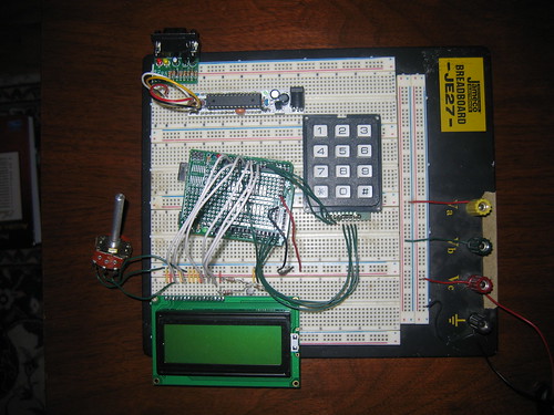
Breadboard with (from top) RBBB serial programming interface; RBBB for driving LED's; 12-key keypad; Arduino with LadyAda prototyping shield; LCD contrast pot and backlight components; 4x20 LCD.Keypad Pin Function Arduino pin 1 Column 2 6 2 Row 0 5 3 Column 1 4 4 Row 3 19 5 Column 0 18 6 Row 2 17 7 Row 1 16 Display Pin Function Arduino pin 1 Vss GND 2 Vdd +5V 3 Contrast adjust See below 4 Register Select 13 5 Read/write GND 6 Enable 12 7 DB0 GND 7 DB0 GND 8 DB1 GND 9 DB2 GND 10 DB3 See below 11 DB4 10 12 DB5 9 13 DB6 8 14 DB7 7 15 LED+ +5V 16 LED- See below terminal/display.sch (Eagle format) and terminal/display.pdf (Adobe PDF).
2 comments:
I was an engineer at the Allen Organ Company for 28 years. I've been enjoying your project! I'm not sure of the practical value, but the important thing is that you're obviously having a lot of fun re-creating the Allen Card Reader!
The thing is that the cards are becoming to fragile to use, so this way, with them already programed, they won't fall apart. We have loads of them, and they are really expensive now, so this way they won't go to waste. :)
Post a Comment