Last time, we got the keypad running. This time, we want to make the display go. The display I chose uses the popular HD44180 controller chip, for which several other Arduino developers have written libraries. But, I observe:
- This display is a little bit different from any of the documented ones. It turns out that the 4×20 display is actually a 2×40 display, with the third line being the continuation of the first and the fourth being the continuation of the second.
- The four-bit LCD libraries that are out there aren't quite debugged - in fact, one that I examined writes the nybbles in the wrong order - how this ever displays anything but gibberish is beyond me.
- I struggle a little with initialization: How to get the chip running in two-line 5×8 character mode, with a 4-bit interface?
Getting the initialization right is the hard part, so let's start there. The issue here is that we're coming up from an unknown state. We don't know what's on the screen, where the cursor is pointing, or what the interface width is. So we need to command a bunch of things. And to do that, since we've wired only four of the display's data bus lines, we need to get the display into 4-bit mode. OK, that's not too hard: writing the nybble 0x2 should do it - change the display from 8-bit to 4-bit, and we're good to send 4-bit commands.
Uhm, no. What if the display was in four-bit mode already? Then we need to write two nybbles to the command register. OK, 0x2 0x8 looks right (4-bit mode, 5x8 characters, two lines).
No, that's not right either! If we started in 8-bit mode, writing the 0x2 will set 4-bit mode, and then 0x8 will be half of the next commmand.
OK, now a light begins to dawn. All of the libraries, including LCD4BIT, begin by setting 8-bit mode several times, delaying in between sending the commands. And their comments don't make it clear why: they all seem to say things like, "the data sheet doesn't say anything about this, but other people do it, and it works." But I get it now: it's to bring the display back to a known state! We could start in one of three possible states: 4-bit mode, 4-bit mode with one nybble of a command sent, or 8-bit mode. Let's just keep sending 0x3 nybbles, and see where it gets us.
Starting from 8-bit mode: 0x3 is interpreted as 0x30 (the other nybble is grounded), and the display goes to 4-bit, 5×8 characters, 1 display line. Then we do the same thing, twice more, leaving the display in that state.
Starting from 4-bit mode: 0x3 0x3 is 0x33, which is still 4-bit, 5×8 characters, 1 display line. (The two least significant bits are ignored.) Then the third 0x3 command is interpreted as 0x30 in 8-bit mode, which is the same as above.
Starting from 4-bit mode with an incomplete command: 0x3 provides the last byte of whatever was being done - taking some unknown action, but that doesn't matter, since we're going to be reinitializing everything. At this point we need a delay to wait for the slowest possible command to finish. The next 0x3 0x3 is a new command, setting 4- bit, 5×8 characters, 1 display line.
So at the end of this sequence, wherever we started, we have the display in 8-bit mode. Now we can put it into 4-bit mode and have everything happy. We just send an 0x2 (interpreted as an 0x20 byte), and now it's 4-bit, 5×8 characters, 1 line. Now from 4-bit mode, we send 0x2 0x8 (interpreted as 0x28) and the display goes to 4-bit, 5×8 characters, 2 lines. Except that when I test it out, it doesn't. Everything else in initialization works, but the display stubbornly remains a 1-line display. Finally, I reread the description of this command in the datasheet, and see the note:
Perform the function at the head of the program before executing any instructions (except for the read busy flag and address instruction). From this point, the function set instruction cannot be executed unless the interface data length is changed.So how do I set character size and display lines for a 4-bit interface? At this point, I'm tired, and disgusted by the revolting mess, and just crawl into bed.
Fast forward to the shower the next morning...
It occurs to me that DB0-DB3 are ignored in 4-bit mode. I don't need to ground them. And since the only 8-bit mode command I execute intentionally is to change the display mode (either to 8-bit or to 4-bit), I can just hard-wire in the nybble I need. Knowing that there's something I can try raises my mood. I finish the shower singing Sailing 'round Yarmouth, and head off to work with a smile.
Sure enough, when I get home and try wiring DB3 to +5 instead of ground, what do I see with the code in the ZIP archive of auxiliary files?
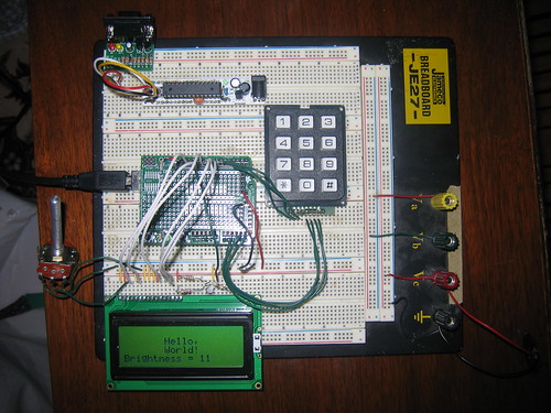
As an afterthought, I also program a few characters into the CGRAM. Describing the length of organ pipes requires at least the vulgar fractions 2/3, 3/5, 1/3 and 1/7. So I know I'm going to want appropriate characters for that. That'll save a few characters of precious screen real estate for each pipe description.
And as a further afterthought, I notice that every time I reset the Arduino, several characters of rubbish show up on the display. A bit of thought reveals that the cause is that the bootloader is flashing the LED on pin 13, which is the same pin that I chose for the ENABLE line of the display. ENABLE gets moved to 14. Another minor annoyance is licked.
No comments:
Post a Comment