The last post described the operator interface box's electronics in nearly finished form. Now we need something to sit in the organ and fire the LEDs. It turns out that it looks pretty easy to do such a thing, because the existing card reader lamps are mounted on a little PC board that is just held in with a couple of 6-32 screws and spacers - and that board is just connected with a couple of wires that provide 8 volt power. Mounting to its mounting points looks a snap.

Taking off the board and looking underneath, I see that the "grain of wheat" lamps stick into holes in the reader case underneath. The holes look to be #29 drill on 1/8 inch centers , and there are holes for the unused card columns (where no lamps are present in the picture). #29 holes are a nice loose fit to T-1 (3.0 mm) LED's. The LED body will go in the hole easily, and the base will not. OK, so what I need is an array of 10 white-light LEDs in that size. As I noted previously, lamp number 8 is displaced toward the rear of the organ.
Aside: I tried a high-brightness green LED for the burnt-out one, but it didn't work. The fact that it didn't wasn't really a surprise. CdS photoresistors - which is what it appears that this device is using - mostly need blue light.
Not having anything suitable in junk, I went and ordered a bunch of white LEDs from All Electronics (Their part number is LED-83.) The data sheet for those says they're supposed to get 20 mA drive current. (Good! An Arduino output can drive them.) And they have a 3.5-4 volt forward voltage. OK, that says that we want to scale the resistor so that it'll source 20 mA when dropping a volt and a half - 68 or 75 ohms ought to do it. The resistor will just be dissipating about 30 mW, so an eighth-watter should be just fine. And I just happen to have ten 68Ω resistors in my junkbox.
The only other I/O that should be needed is some sort of communication with the display unit. My criteria for this: a reasonably thin cable, a fairly robust, small and readily available connector, and no tying up the on-board UART on either the terminal or the LED controller. (I want to have access to the 'Serial' library when debugging!) A little bit of headscratching, and I decide that an old PS/2-style keyboard connector should be perfect. The PS/2 keyboard protocol is fully synchronous (with the keyboard generating the clock), so there's no need for accurate timing on the receiver - just shift in the bits on an interrupt. (That also means that I want at least the clock line on an interrupt-capable pin, so pins 3 and 4 become the PS/2 interface).
With this much settled, I've got a complete schematic.
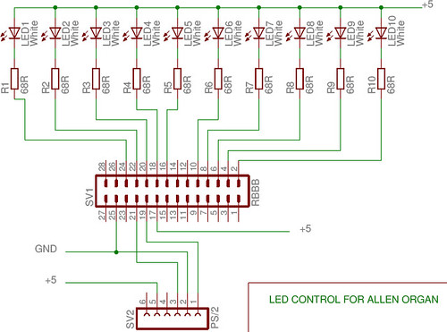
The pinout on the PS/2 port is standard with one exception: I've changed the Vcc lead from +5 to the unregulated 9V input. That'll give me a ready way to power the display terminal through the cable, even though there's an LED backlight (240 mA) to run.
I also do identical wiring for the PS/2 connector over on the display side. So now I've got a communication channel. Next comes programming that channel.
No comments:
Post a Comment