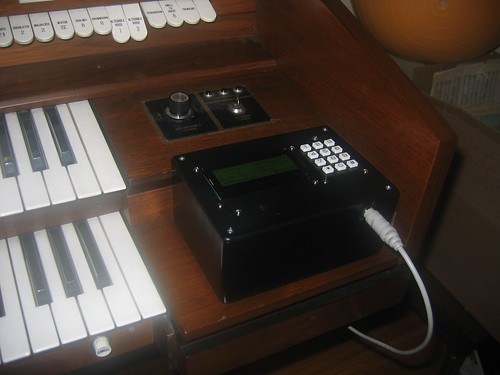
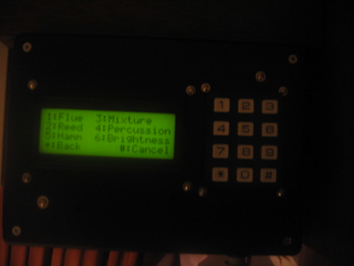
It sits there on the organ console, looking as if it was built to go there. Well, it was.
Mounting keyboard and display was a matter of screwing in a whole bunch of #2-64 screws and nuts:
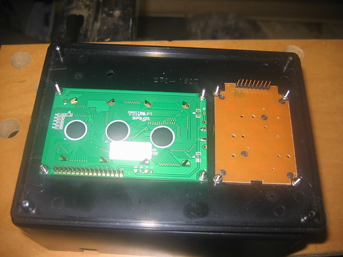
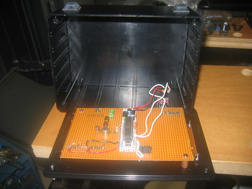
Then wiring the circuitry was a pretty routine perfboard job. The front of the board (toward the front panel) has sockets for the keypad and display, and mounts the trimpot that controls display contrast. It also has most of the actual wiring. There's a little scorch mark on one wire that would not stay out of the way of the soldering iron. Nobody's going to see it inside the box, and it's not near anything that's going to short it, so I'm just going to leave it alone. Nobody's perfecʇ.

The back of the board (the side that faces the inside of the box) mounts the RBBB, the DIN jack for the PS/2 keyboard cable, and a 4-pin socket where the serial interface goes for flashing the firmware.
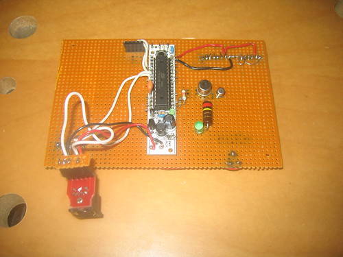
Of course, I wound up making up some circuit modifications while I was wiring it up.
First off, I rearranged the pin assignments to give a neater layout on the perfboard with the RBBB turned sideways.
Next, I added a 470 Ω resistor and green LED to provide a 2.5 Hz "blinky light" status indicator that shows the firmware's main scan loop is running. (I've half a mind to have it send the firmware revision number in Morse.)
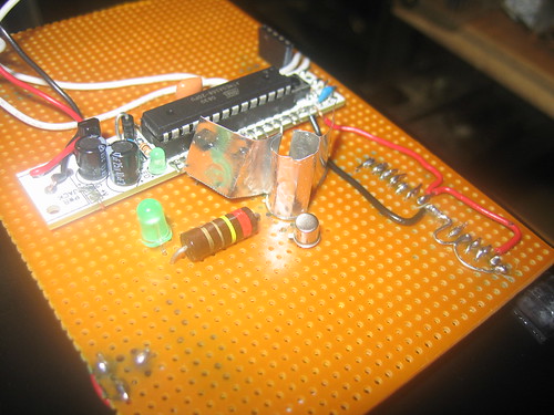
Finally, I decided that driving the LED backlight for the display - which is rated for 240 mA at a 4V forward voltage - off of the voltage regulator on board the RBBB was a losing proposition. Instead, I put together a little current regulator circuit. The 2N3053 transistor (good for a couple of Watts of collector dissipation) is switched with base current supplied from an RBBB pin via the 2.2K resistor. The 2.7Ω 2W wirewound resistor (it's mismarked 2.4Ω, which is why it turned up in surplus!) senses the emitter current. When the drop across it exceeds the Vbe of the little 2N2222A transistor, the little transistor turns on and robs the base current from the big one. Result is that the LED is driven at a 240 mA constant current, and then is pulse-width modulated for brightness. It's both brighter than the 6.8Ω resistor made it, and more stable with supply voltage and temperature fluctuations. Only thing is that the 2N3053 pass transistor was getting a little warm (on the borderline of exceeding the safe operating area of the "fingertip thermometer"), so I added a little homemade heatsink cut out of aluminum foil from a pie plate in the recycle bin. This technique works pretty well for medium-size devices as long as you use lots of grease to get good thermal contact with the foil.
The board goes into the project box, held in place by the keypad and display sockets in two corners and #4-40 screws, nuts and washers on fiber standoffs in the other two corners.
So now I try to flash the firmware (with the revised pin assignments). And ... nothing! Nada! Bupkis! The TX light flashes a couple of times, and avrdude refuses to sync with the chip. Several hours of puzzlement ensue.
Oh, [Nixonian expletive deleted once again]. I already made this mistake once, with the other RBBB inside the organ! And I've gone and done exactly the same thing again. I have RX and TX interchanged. (RX on the Ladyada serial interface goes to TX on the RBBB, and vice versa. Only this time, when I correct it - still nothing. Yes indeed, I've blown the chip. It's pretty forgiving, but this was too much for it.
Oh well, I still have one more Atmega168, sitting in the Arduino. (And I've been wanting to upgrade that one to a 328 anyway). So I swap chips...
And the display shows the menus nicely, and programs the organ.
I won't say that the firmware is done, but it's getting there. The big pieces that I want to add are that there's nothing behind menu #5 (where I want to put Hammond drawbar registrations), and I want to add an interface for scaling stops (making them louder or softer). Aside from that, though, it's more usable than the card reader - I don't have to worry about cards falling apart and lamps burning out.
I'm a happy camper for the moment.
A big thanks to Steve for getting me started with his surplus Arduino stuff, and to Carl K2YR for the fabrication assistance (and circuit sanity checking and general willingness to serve as the teddybear that I explain things to).
And, of course, thanks to Mary Ann and Cathy for putting up with all this geekiness.
8 comments:
I think your Allen organ project was GREAT! After searching the net high and low, I finally came upon your blog. Would you mind sharing your results (schematic, code, etc)? I've been an organist for 30 years and my current church has an Allen MOS-1 I would like to upgrade.
Tried to send you an email with link to the files. Shoot me an email back at kennykb@acm.org if you didn't get it.
Hi,
I recently purchased an RMI Keyboard Computer 2, which also uses the MOS 1 board and punch card reader. I was also interested in what alternatives there might be to punch cards and it was with great pleasure that I came across your most informative and impressive blog.
Suffice to say, I'm hoping to repeat the project and, not wanting to just piggy back on all your wonderful work, hoped we could make an amicable arrangement towards implementing this for a 2nd time?
The links to the firmware source code no longer work, so that's one thing. I am a coder, so I may be able to give something back in that department. However, my electronics isn't as good (I did get a Rhodes EK10 back to 100% working though) so I might need some support from yourself and/or my synth repairer (who seems fascinated by the RMI KC2:) Of course, if you're up for building another, then I'm sure we can work something out there too.
Anwyay, hope you have some availibility for this and look forward to hearing from you.
Yeah, I reorganized my personal site some time ago.
The firmware and schematics are still there:
http://kbk.is-a-geek.net/fossil/organ/zip/OrganProject.zip?name=trunk
Drop me a line if it doesn't work.
Unfortunately, it's unlikely that life will allow for me to build one for you. I'm going through a bad period in my personal life and don't have very much time for side projects at the moment. (In fact, I'm also abysmally out of practice at the organ, for much the same reason!) The whole thing is actually a fairly easy build, though. There's no tough surface soldering, everything is through-hole on at least 0.1 inch centers. And I think I left the firmware source in decent shape.
Don't be afraid of 'piggybacking.' I posted the project because it was fun. I don't mind at all if anyone else wants to build one.
Oh, and I'm perfectly willing to try to give you guidance, if you can put up with erratic response times. Shoot an email to kennykb at acm dot org if you need help.
Hi Kevin.
Sorry to hear about the personal crisis - problems reserved for the best of us I'm sure;)
Many many thanks for the response and link to the code. Download was fine (with ?name=trunk removed). I think the only other goodies needed alongside this are the arduino software here: http://arduino.cc/en/Main/Software
and to execute the tcl file you may also be needing http://www.activestate.com/activetcl/downloads which worked perfectly for me with the provided tcl file.
I see excellent RBBB instructions in your link too which is terrific as this bit of circuitry was the other thing I was unsure about.
In short, I think that's everything in place to give this a go and for a very deserving candidate in the RMI KC2 (<100 made, fantastic sound quality, and a piece of history as you know from the MOS1 organs).
So, if you don't hear from me before, I'll certainly pitch back when I get to crowing (though I'm sure I won't match your particularly fine crowing effort!) and, of course, will post back any nuggets I find along the way.
Many thanks once again for making this terrific project possible and for the continued support.
Hello nicce post
Post a Comment