
From left, the major components are a serial adapter for flashing the firmware, the RBBB itself, and the LED array. For the breadboard, I didn't bother to attach the PS/2 connectors, instead directly wiring pins 3/4 between the Arduino and the RBBB, and the power supply rails (note the jumpers at the right hand edge). The LED pins in the picture were chosen for convenience on the breadboard and aren't the final pin assignments on the reader.
The first task is to make the LED control respond to commands from the display unit. This means firmware changes for both the boxes, of course.
The code baseline for these changes is over at http://kbk.is-a-geek.net:2303/ci/ac332e3e60, if you want to follow along.
I'm letting the display box play "keyboard", and the LED control play "computer". I'm following the PS/2 keyboard protocol loosely (not bothering to implement things like retransmit request, and of course, keyboard scan codes will be meaningless in this application). But the wire protocol is pretty much the same.
When the line is idle, both ends have DATA and CLOCK pulled to +5 through (nominally) 15K resistors. (I'm using the internal pullups on the microcontroller.) We're simulating 'open collector' ports, so from the Arduino's perspective the HIGH state is:
pinMode(pin, INPUT);while the LOW state is:
digitalWrite(pin, HIGH); /* high impedance with pullup */
pinMoode(pin, OUTPUT);When the keyboard sends a byte, the procedure is shown in the diagram below. (In this case, the terminal is sending an ASCII 'U', 0x55.)
digitalWrite(pin, LOW); /* low impedance pull to ground */
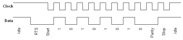
The terminal begins by pulling the DATA line LOW, to request to send. It waits for at least 50 microseconds, and tests that the host has not pulled the CLOCK line LOW to forbid transmission. (The host can do this at any time, and the terminal checks before pulling it LOW and after returning it HIGH.)
The terminal then sends an 11-bit data frame. Each bit (except for the 'start' bit, which is already there) is placed on the DATA line on a LOW->HIGH transisiton of the CLOCK line. The host clocks the bits out on the falling edge of the CLOCK line, when the terminal is holding them stable.
In order, the bits are:
- 1 : Start - always '0'
- 2-9 : 8 data bits, present least significant bit first
- 10 : A parity bit, chosen so that there is an even number of '1' bits in bits 2-10.
- 11 : Stop - always '1'
The clock speed can be anywhere from 10 to 16.7 KHz, so the transitions are spaced anywhere from 30 to 50 microseconds apart. The terminal just uses 'delayMicroseconds' to insert the necessary time delays. The LED controller attaches an interrupt to the falling edge of the clock, and has a timeout activated from its scan loop to detect incomplete data frames.
There are four possible errors that the controller can detect when a data byte arrives.
- Parity error - an odd number of '1' bits was present in the frame - the number should be even.
- Framing error - the stop bit was a '0' - it must always be a '1'.
- Timeout - the data frame did not complete within 150 ms.
- Overrun - there was no buffer space available to store a newly-arrived byte.
- 'S' - Set stop. The 'S' is followed by 32 hexadecimal digits giving the wavetable from the punched card.
- 'T' - Test. The 'T' is followed by arbitrary text. The command is simply echoed to the serial port. It's there for debugging.
- 'W' - Wake up. This command brings the controller out of its 'standby' state - which means turning on the LEDs and delaying briefly for the organ to detect that the card slot is unobstructed. No data are expected between the 'W' byte and the newline.
- 'Z' - Zzzleep. This command brings the controller into 'standby' after the display has been idle for 30 seconds. It turns off the LEDs to save power. No data are expected between the 'Z' byte and the newline.
No comments:
Post a Comment