
I started by printing a template on paper and putting it on the panel with spray glue. That gave me all the cut locations neatly laid out. As I did the template, I even remembered to displace the display unit a little bit upward so that the pins of the display and keypad lined up to holes on 0.1 inch perfboard.
Next came drilling some 5/16" holes in the middle of the two rectangular cutouts that hold the keypad and display. Then it was crunch-crunch-crunch with an Adel nibbling tool making rectangular cutouts that were (intentionally) a shade too small. (I can cut away more material, but it'd be real hard to put any back!) Then, with a file and patience, I enlarged the holes until they gave a snug fit for the components. (The keypad has a radius on each corner, and I just made that with a Dremel tool).
I used the components themselves as templates to mark the locations for #42 holes for the 2-64 mounting screws that hold the keypad and display, and drilled holes to mount the perfboard and to provide screwdriver access to the display contrast control. The screw holes came out a little ragged, what with being drilled from the wrong side, but the screw heads will cover that up anyway.

The fit of the perfboard inside is "perfect enough." If you click through to the original photo, you can see the socket pins lined up with the holes. That'll give me a base to wire on. The two nylon studs are for mounting the RBBB. [UPDATE: Decided not to use them, and just mount the RBBB flush to the perfboard.]
I also machined a slot into the side of the box below the keyboard to hold the DIN connector for the PS/2-style keyboard cable, and a mating groove on the connector. That one worked out nicely. The connector feels like a rigid fit even without backing it up with hot glue, which I plan to do anyway.
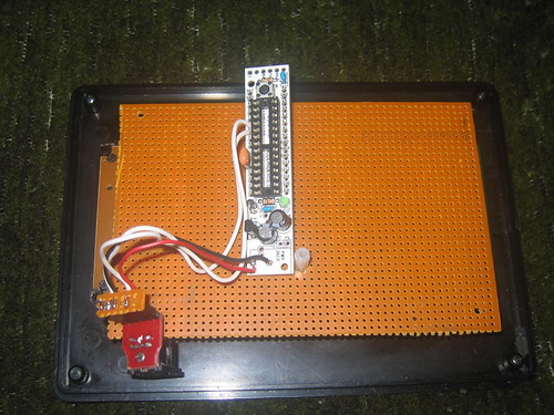
And I got another RBBB built. I soldered a 6-pin female connector to go to the DIN connector breakout. This box draws its power from the DIN connector and has the data lines going to two of the digital inputs. You can see where I ground away the breakout board so that the slot in the project box can engage the groove on the connector body. (Grinding a FR-4 fiberglass board takes patience and a dust mask.)
Plugging the DIN connector into the LED controller, the pilot light on the power supply lights and the Vcc pins check out at 5V, so I guess I got that part right.
No comments:
Post a Comment