When the controller is idle, all the LED's are on, as if there is no card in the slot. (Among other things, this convention allows me to continue programming the organ with cards, if I wish.)
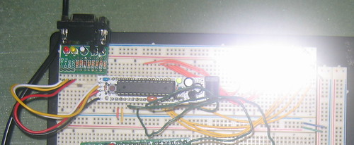
Wow, those LED's are bright.
Now, let's look in detail at what happens when a card is inserted and removed.
[Update: I was wrong about the quadrature signal. The next post explains.]
- First, the paper blocks all the lamps (LEDs are all off). This condition persists until column 6 lines up with the photoresistors.
- Next, for each group of three columns, the row 9 hole, and the data in rows 0-6, come into view. LED 9 and the data byte are lit.
- The row 8 hole comes into view early, because its photocell is displaced half a column. LED 8 lights.
- The data column leaves the photocells (LEDs 0-6 and 9 go off).
- The timing column leaves the photocell (LED 8 goes off).
- About 1 1/2 column of blank space (all LEDs off) passes over, and then the cycle repeats for the next fifteen data bytes.
http://kbk.is-a-geek.net:2303/ci/41508259dd has the code baseline that does this. With the clock rate slowed down to where my human eyeball can track what's going on, the data look right.
Now to move the thing onto the card reader and try it out on the organ!
No comments:
Post a Comment