The LEDs need to be on quarter-inch spacing, while the perfboard hole spacing is 0.1 inch. But quarter-inch spacing is easily done by mounting every other LED on a diagonal pair of rather than a h0rizontal pair. The row 8 LED (second from top in the picture) is mounted vertically, which displaces is 0.05 inch toward the rear of the organ.
With a little tweaking, the LEDs fit the holes in the card reader beautifully:

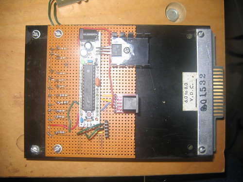
The LED pin numbering was a little inconvenient for the perfboard layout, so I did a quick firmware flash to renumber them.
And the PS/2 communications crapped out. I'm getting spurious interrupts.
After a couple of evenings of very frustrating debugging, I finally get it. When I put in the keyboard cable, rather than the short wires on the breadboard, I added enough capacitance that the LOW->HIGH transition got really sloppy (remember, these are open collector outputs!). Adding a line of code to drive the pin HIGH at low impedance for a brief period (just long enough to change the pin mode to INPUT) makes the transition clean enough that the spurious interrupts go away. The data transmission looks solid as a rock.
And as I was testing to make sure that the card slot was unobstructed, I realized.
The photocell for LED 8 is displaced to the rear. Not the front. So it's not in quadrature with the others. Instead, it gets fired independently when all the others are off. A quick bout of editing and another few firmware flashes. (Slow the clock down again, to watch the lights blink, and then speed it back up. Plus debugging.)
The firmware is now at http://kbk.is-a-geek.net:2303/ci/95f796cc4d.
And it's time to try this thing out for real!
No comments:
Post a Comment